


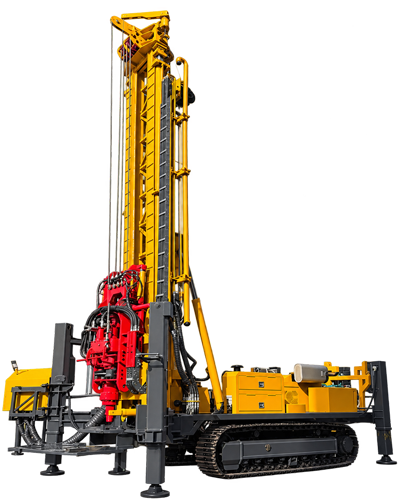
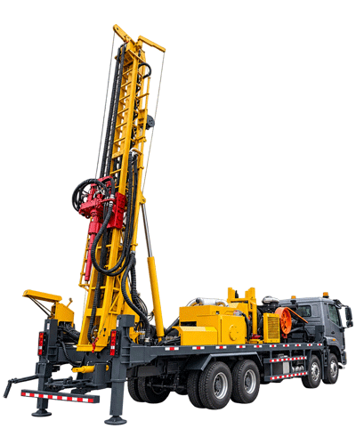
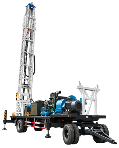
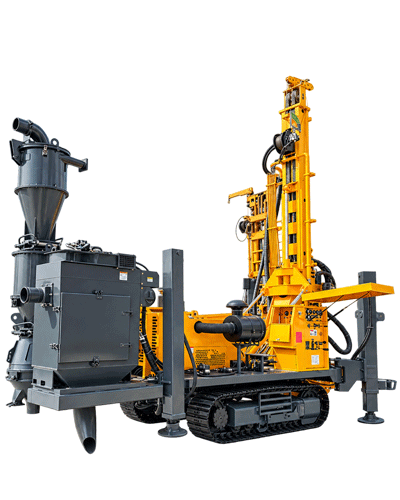
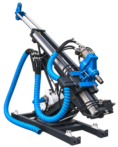
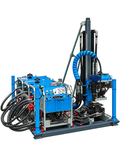
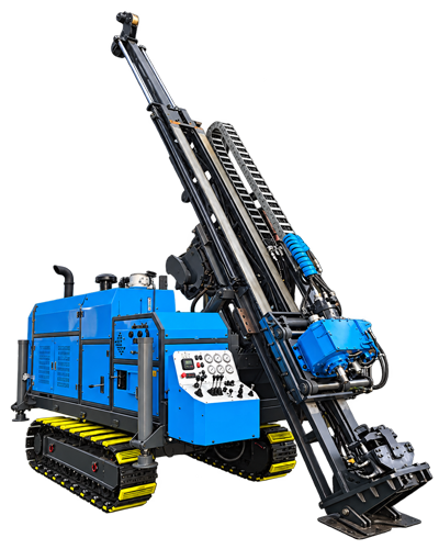
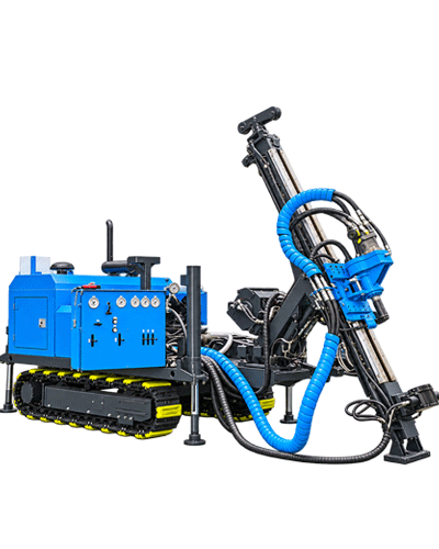
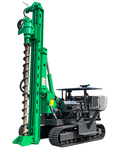
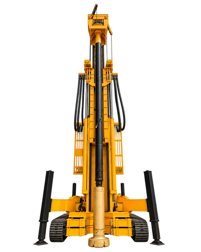
When reviewing the public documentation for the RC600-CS3, the sampling section describes how cyclone separation, sample splitting, and bagging are connected into a continuous process, while the drilling section states a maximum drilling depth of 600 m, a hole diameter of 105–450 mm, working angles of 45°/90°, and also includes values such as 29 T lifting force, dual-condition torque of 12000/6000 N·m, and air consumption of 16–75 m³/min. These contents are not in the same location. If the sampling paragraphs and drilling paragraphs are read separately, it is easy to treat "having a sampling system" and "being able to drill a 600 m hole" as two unrelated matters. In fact, both share the same sample return channel and the same set of in-hole conditions. This article follows the organization of the documentation itself to provide a reading order, explaining which section to read first, which to read next, and which values must be read together.
Read the sampling first: which actions the three-in-one system connects
The documentation describes the CS3 three-in-one system as follows: after cuttings return to the surface through the inner tube of the dual-wall drill pipe, they enter the cyclone system for gas-solid separation, then enter the sample splitting and bagging stages. In other words, this system integrates cyclone separation, representative sample splitting, and sample collection into a continuous process, with the purpose of reducing manual sample transfer and secondary handling. The documentation uses "mineral exploration projects with large daily sampling volumes" to illustrate its more suitable applications; this is a description of use, not a conclusion that holds for every project.
When reading this section, first distinguish the objects handled by each of the three actions: the cyclone handles the gas-solid two-phase flow, the splitter handles the already separated solid sample, and bagging handles the correspondence between samples and numbering records. The three actions in series indicate that a manual transfer step is eliminated, but they do not specify whether splitting precision or sample representativeness meets any standard—these are not provided in the documentation and require separate confirmation.
Then read the depth: 600 m and 105–450 mm must be considered together
The documentation states the maximum drilling depth of 600 m and hole diameter of 105–450 mm as "this range can cover most medium-to-deep mineral exploration holes and can also handle some large-diameter water wells." The same paragraph also includes a key qualification: actual drilling depth will vary with hole diameter, dual-wall drill pipe weight, air compressor capacity, and formation conditions. This statement indicates that 600 m is not an upper limit that holds for any hole diameter; when reading, the depth figure cannot be taken alone as a capability conclusion.
| Documentation item | Value or range | Which section it affects |
|---|---|---|
| Maximum drilling depth | 600 m | Total length of the drill string in the hole and tripping load |
| Hole diameter | 105–450 mm | Hole diameter and depth constrain each other; actual hole depth is usually shallower with large diameters |
| Working angle | 45° / 90° | Hole direction is determined by geological design; inclined holes affect outrigger loading and hole direction control |
| Recommended air consumption | 16–75 m³/min | Whether deep-hole sample return is continuous; insufficient air volume manifests as reduced or delayed sample return |
| Recommended working air pressure | 1.6–6 MPa | In addition to driving the RC hammer, it must ensure cuttings can continuously return through the inner tube |
This table is not a capability ranking but a reminder: hole diameter, hole depth, angle, and air supply all hold simultaneously in the same hole; citing any single row alone will lose the constraints of the other rows.
What maintains sample return: the relationship between air consumption and drilling depth
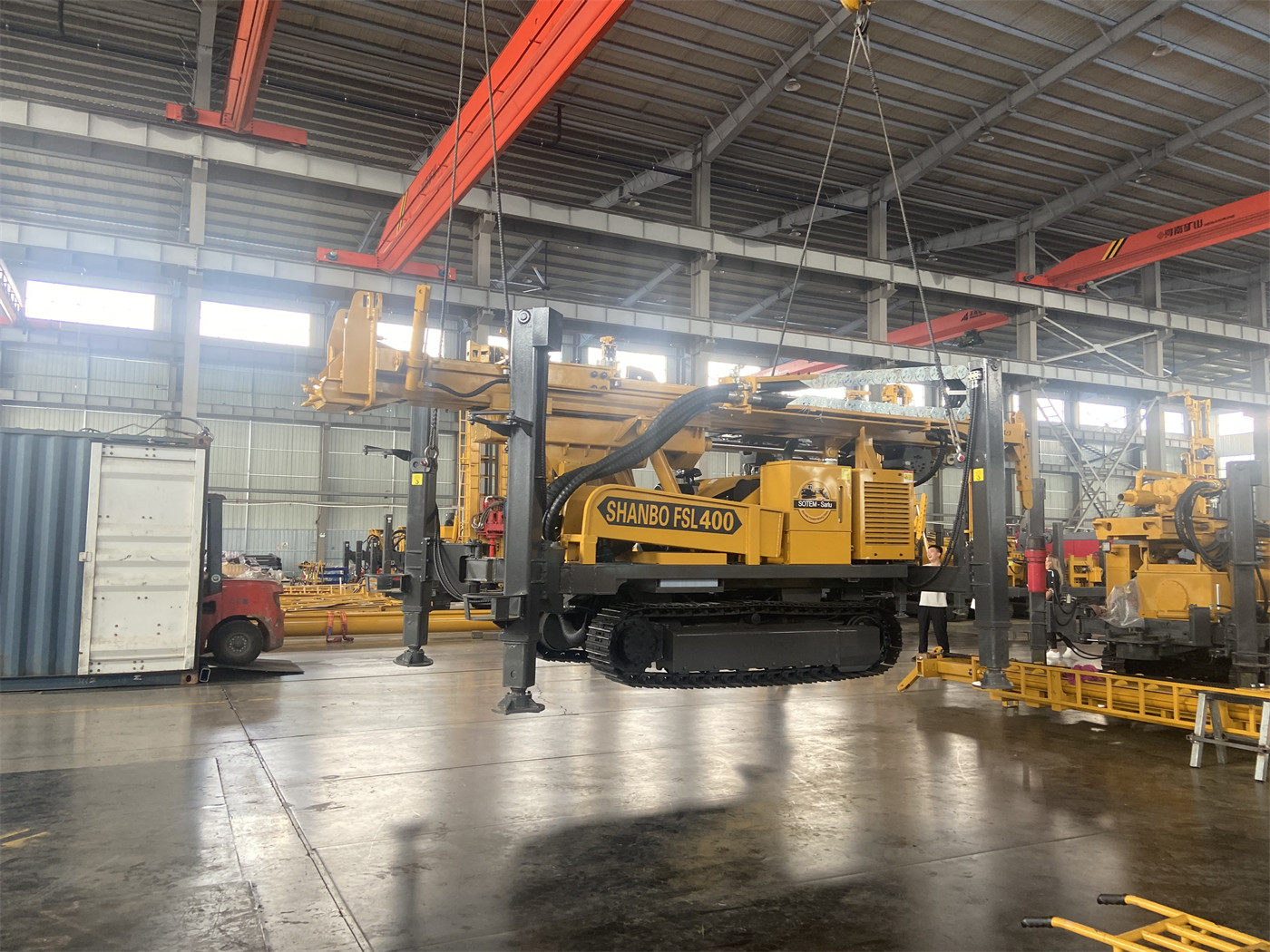
In the section "600 m class reverse circulation sample return places more emphasis on deep-hole stability," the documentation states that as hole depth increases, the cuttings return distance becomes longer, and air volume loss, drill pipe sealing, and in-hole air leakage have a more noticeable impact on sample recovery. The subsequently given air consumption of 16–75 m³/min and air pressure of 1.6–6 MPa are not only for driving the RC hammer but also for ensuring cuttings continuously return through the inner tube to the cyclone sampling system.
This section directly links the sampling process with drilling depth: the three-in-one system can handle the samples returned, but whether the samples can return to the surface depends on whether the air supply end meets deep-hole conditions. The documentation lists the manifestations as reduced sample return, delayed sample return, and bottom-hole cuttings accumulation, and notes that air compressor selection should fully consider hole depth, hole diameter, and altitude. For altitude, the documentation only mentions it needs to be considered and does not provide correction values.
Lifting force, torque, and working angle: three parameters constraining tripping and hole direction
The 29 T lifting force corresponds to tripping, RC hammer recovery, and some casing operations for 600 m class dual-wall RC drill pipes. The documentation also explains that the dual-wall RC drill pipe structure is more complex than ordinary single-wall drill pipe, and the entire string weight and friction are higher in deep holes. The purpose of this statement is to explain why lifting force needs to be considered separately rather than treated as a negligible auxiliary parameter.
The 12000/6000 N·m corresponds to rotation speeds of 75/150 r/min. The documentation positions low-speed high-torque for large-diameter, high-resistance, and hard-rock hole sections, and higher rotation speed for stable formations with lighter loads. The 45°/90° working angles appear together with an outrigger stroke of 1.7 m: the documentation explains that in inclined holes or high-torque drilling, the force direction on the entire machine is more complex, and outrigger loading and platform stability affect hole direction control and operational safety. Only by reading these three items as a group can one see the layer of "whether it can remain stable" beyond "how deep it can drill."
When sample depth does not match, the problem may not be in the sampling system
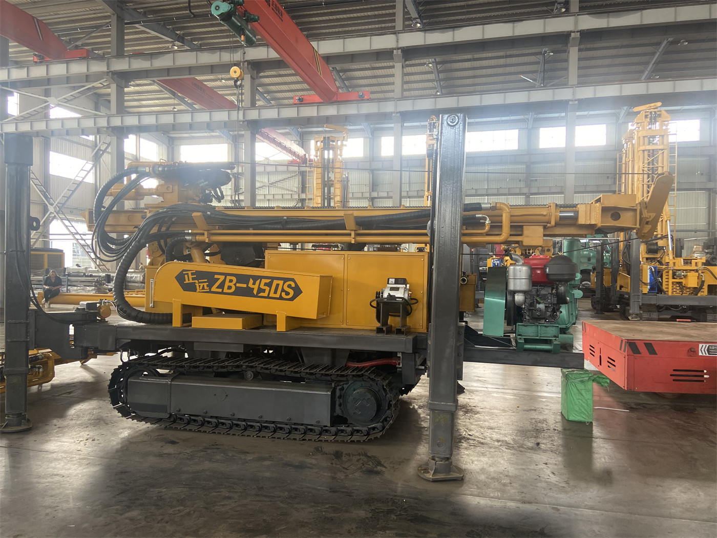
In the section on fractured zones and air-leakage formations, the documentation points out: fault fracture zones and large fissures can cause air leakage, and cuttings may remain in the hole and then return in concentrated batches, causing poorer correspondence between samples and actual depths. The significance of this item for reading the documentation is that it explains the three-in-one system handles samples that have returned to the surface, while when samples return to the surface is affected by in-hole air leakage and hole cleaning conditions.
Correspondingly, in the sample management section, the documentation requires each sample bag to be labeled with hole number, sample number, start and end depths, date, and shift, and to set duplicate samples, standard samples, and blank samples according to project requirements; each time drilling is stopped, the hole is changed, or a new key sampling interval is entered, check whether there is residue inside the cyclone, splitter, and sample return hose. These are management actions explicitly stated in the documentation, not suggestions added by this article. Collecting samples at fixed intervals of 1 m or 2 m is also an example listed in the documentation, not a mandatory requirement.
Hole wall and formation: alternative processes beyond RC
The applicable formation given in the documentation is written as "soil," and it also explains that soil layers, clay, sand layers, and gravel layers are prone to hole collapse and may not be suitable for direct high-air-pressure RC drilling; the equipment supports mud rotary, so mud and casing can first be used to stabilize the upper hole section, then switch to RC or DTH processes after entering rock. For hard rock, it states that granite, limestone, sandstone, and other relatively intact rock formations can use RC hammers or DTH down-the-hole hammers, and distinguishes that RC hammers are more suitable for exploration holes requiring continuous samples, while ordinary DTH hammers are more suitable for water wells and general boreholes where sample quality is not emphasized.
This content determines process selection, not the upper limit of equipment capability. When reading the documentation, if one only sees "reverse circulation drill rig," it is easy to overlook that it also has two alternative paths: mud rotary and DTH; however, the documentation does not provide drilling efficiency for each process, so construction speed cannot be inferred from these descriptions.
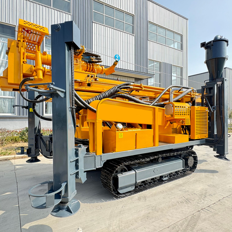
Water well use and sampling use: two ways to read the same equipment
The documentation clearly states that the RC600-CS3 can also be used for deep water wells in agriculture, industry, and mining areas, and explains that water well projects focus more on hole wall stability, aquifers, and well completion structure, and "do not necessarily require activating the complete sampling system." This sentence should be marked separately when reading this documentation: for the same equipment in two types of projects, the parameters and procedures of concern are not the same. Water well projects require separate confirmation of well location, well diameter, and completion structure; mining area dewatering projects require determining well location, well spacing, well diameter, and pump capacity based on hydrogeological conditions, and the documentation explicitly states "the drill rig is only responsible for hole completion and cannot replace complete dewatering design."
Supporting equipment and site: how far the documentation goes
The overall machine information given in the documentation includes a 132 kW Cummins engine, a crawler travel speed of approximately 3.5 km/h, a maximum climbing angle reference of 21°, an overall weight of approximately 12.5 T, dimensions of approximately 7 × 2.1 × 2.9 m, and a winch lifting force of 2.5 T. The supporting descriptions related to sampling are: the site also needs to accommodate an air compressor, cyclone sampling system, sample bags, and transport vehicles, and the drilling platform should reserve sufficient area to ensure smooth sample return piping and safe personnel access.
- Air compressor: the documentation only gives recommended air pressure and air consumption ranges, not specific models; selection should take hole depth, hole diameter, and altitude into consideration.
- Sample area layout: the documentation mentions that the sample area is usually close to the drill rig and cyclone, and during lifting, suspended objects should be kept out of the sampling personnel's work area.
- Transfer roads: the documentation gives crawler travel speed and reference climbing angle, and also states that before transfer, road load-bearing capacity, slope, and soft ground conditions should be confirmed.
- Maintenance: before daily start-up, check dual-wall drill pipe seals, sample return hoses, cyclone, splitter, engine, hydraulic system, and high-pressure air lines; these are daily maintenance points listed in the documentation.
What the documentation does not answer
The following points have no corresponding values or conclusions in this documentation and should be treated as items to be confirmed when reading, rather than inferred from existing parameters:
- Whether the 600 m drilling depth can actually be achieved under different hole diameters and formation combinations; the documentation only states that actual drilling depth will vary with conditions.
- The splitting precision and sample representativeness indicators of the splitter, and whether they meet the QA/QC requirements of specific projects.
- Correction methods for air consumption and power configuration under high altitude, high temperature, or low temperature environments.
- Specific air compressor models, supporting drilling tool specifications, and cyclone processing capacity.
- Specific parameters and quantities for treatment methods such as foam and casing in air-leakage formations.
Reading this documentation as a chain, the order is roughly: first confirm whether the project requires continuous cuttings samples or well completion, then see which stage of the sampling process requires on-site management, then check drilling depth, hole diameter, angle, and air supply under the conditions of the same hole, and finally implement air compressor, site, and maintenance support. The documentation can support these judgments; matters beyond this scope require separate confirmation with the manufacturer and on-site geological conditions.