

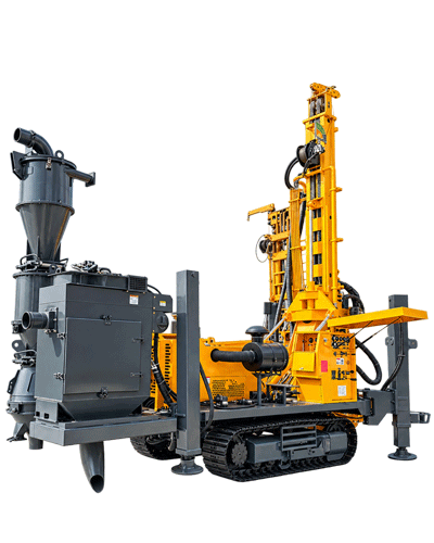
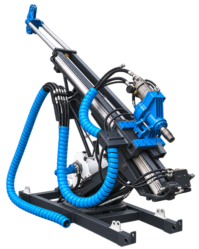
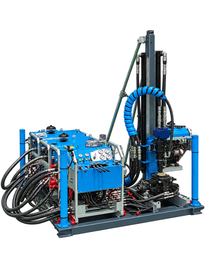
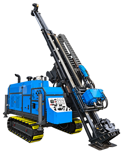
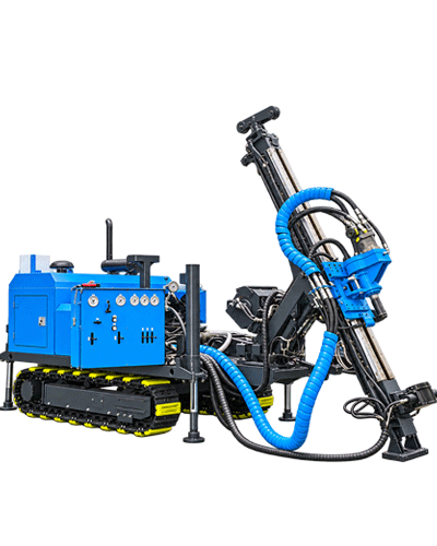
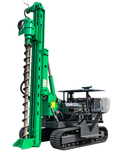
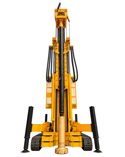
A water supply well planned for a depth of four to five hundred meters is often reduced to a single question during the equipment inquiry stage: is the rig's drilling depth sufficient? But what really determines whether things go smoothly later is often not the drilling depth figure itself, but how much water the well needs to produce, what diameter the completed well will use, and how much load the drill string must bear in the hole. Water supply scale and well depth together determine the lower limit of equipment capability, and drilling depth is only one of the externally visible indicators.
This article follows the sequence of "first set the water supply target, then determine the diameter structure, and finally match equipment capability" to break down the selection process for mid-deep well equipment classes, and uses public information on the WR450SE to explain which parameters these conditions fall under. The judgments in this article are project analysis, not actual construction records of any specific project.
Step 1: Derive the completed well diameter from the water supply scale, rather than looking at drilling depth first
A water supply well must meet the water extraction requirement, and the extraction rate is tied to the completed well diameter, filter pipe specifications, and submersible pump outer diameter. If the diameter is too small, the pump cannot go down and the filter pipes cannot be arranged; expanding the hole later is very costly. If the diameter is too large, the load on drilling tools, cuttings removal, and air supply will increase, and the equipment class must change accordingly.
Therefore, the first step in working backward is to convert "how much water must be produced per day" into "what completed well diameter is needed and how deep the pump must be installed." The borehole diameter range given in the WR450SE data is 105–400 mm, and this range covers common structures from smaller-diameter water supply wells to larger-diameter irrigation wells and livestock water supply wells. Where the diameter falls within this range directly determines which level of rotary and air supply conditions must be checked later.
Step 2: Use well depth to determine drilling depth margin, rather than treating drilling depth as a construction target
After the target well depth is determined, the equipment's drilling depth usually needs a certain margin. The reason is not "drilling a few dozen extra meters," but rather uncertainty in aquifer location, the possible need to deepen the completed well structure, and the need for handling room when abnormalities occur in the hole. The maximum drilling depth of the WR450SE is 450 m, placing it in the 450-meter class of mid-deep hole equipment. For projects with planned depths of three to four hundred meters and unstable aquifer distribution, the extra drilling depth margin this class has over 300-meter and 350-meter class equipment is mainly to leave room for water exploration and completed well structure; it does not mean every well must be drilled to 450 m.
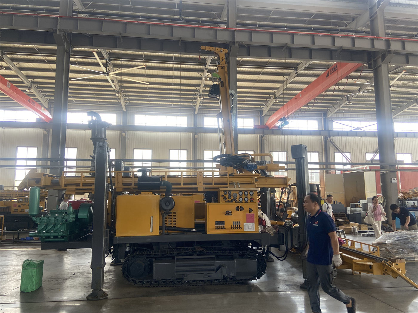
It should be noted that drilling depth is the upper limit of equipment capability, not the project target. Whether it is worth moving up to this class also depends on whether the following capabilities are simultaneously satisfied.
Step 3: Put diameter and well depth back into the same capability checklist
Looking only at drilling depth or only at diameter easily leads to one-sided conclusions. Only by putting water supply scale, completed well diameter, and target well depth together can one judge whether the equipment class matches. The table below is a correspondence organized from public WR450SE data, for item-by-item verification during selection.
| Operating condition | Corresponding equipment capability item | Reference value in the data |
|---|---|---|
| Target well depth and aquifer depth | Maximum drilling depth | 450 m |
| Completed well diameter and well casing, pump type | Borehole diameter range | 105–400 mm |
| Drill string dead weight and tripping operations | Lifting force | 20 T |
| Changes in diameter, rock properties, and resistance | Dual-condition rotary torque | 9000 / 4500 N·m; 90 / 180 r/min |
| Drill pipe connection frequency and hole depth | Drill pipe length | 6 m, recommended diameter 89 / 102 mm |
| Hard rock DTH hammer drilling | Working air pressure and air consumption | 1.2–3.5 MPa; 16–55 m³/min |
The purpose of this table is not to check off each item, but to see whether any item is already approaching its limit. If the diameter is close to 400 mm and the well depth is also close to the equipment limit, then lifting force, torque, and air supply will all be tight at the same time. At that point, the question is not "is drilling depth sufficient," but whether the entire set of capabilities still has margin.
Step 4: The drilling process determines supporting conditions, and supporting conditions in turn constrain equipment selection
Mid-deep water supply wells are rarely completed using only one process. The upper overburden is often drilled with mud rotary for wall protection, and after entering more intact rock formations, the process switches to a DTH hammer. The WR450SE data provides corresponding explanations for both sections: soil, clay, and sand layers can use mud rotary; more intact rock formations such as limestone, sandstone, and granite can be equipped with a DTH hammer and bit. Only when the processes can connect does the equipment have practical significance.
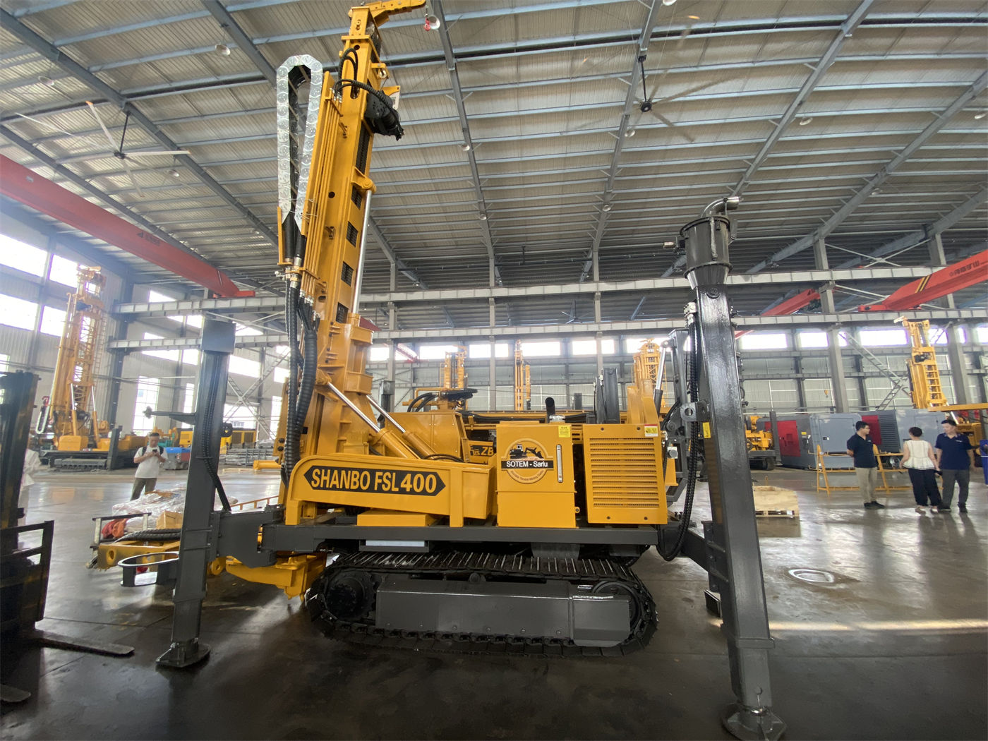
This also means selection cannot look only at the complete machine. Accessories such as mud pumps, air compressors, and foam pumps must be combined according to the main operating conditions: projects with more loose layers rely more on mud pumps, hard rock projects rely more on air compressors and DTH hammers, and hole sections with severe air leakage may require foam assistance. The data clearly states that these are optional items and should not be assumed to be supplied as standard with the complete machine.
Why this equipment class is worth including in comparison when conditions match
Based on the verification logic above, several features in the WR450SE data directly correspond to the needs of mid-deep water supply wells:
- 450 m drilling depth with 105–400 mm diameter covers the structural range of mid-deep water supply wells from smaller to larger diameters, so there is no need to change class immediately when water supply scale changes.
- 6 m drill pipe reduces the frequency of pipe connections in mid-deep hole construction. As hole depth increases, the impact of the number of drill pipe make-up and break-out operations on effective construction time is amplified, and longer drill pipes are more meaningful for continuous construction of multiple mid-deep wells.
- 20 T lifting force is used for tripping conventional drill pipes in the 450-meter class, recovering DTH hammers, and some casing operations. As hole depth increases, both drill pipe dead weight and borehole wall friction rise, and this capability is a basic condition for handling drill strings in mid-deep holes.
- 9000 / 4500 N·m dual-condition torque corresponds to different diameters and formations: the lower-speed, high-torque state is suitable for large-diameter, hard rock, or higher-resistance hole sections; the higher-speed state is suitable for stages with relatively lower resistance. This is not the concept of a two-speed gearbox, but a basis for switching between two operating conditions.
- 92 kW power and approximately 8.5 T complete machine weight lean toward practicality and cost balance in 450-meter class mid-deep hole projects, while being easier to organize for transfers across townships and farms than larger equipment.
Applicable boundaries: which conditions push this equipment class beyond its limits
Conditional judgment is more useful than general recommendations. The following situations require re-evaluating the equipment class:
- Target well depth consistently exceeds 450 m, or aquifer depth is uncertain and a larger water exploration margin is needed; a higher drilling depth class should be considered.
- Completed well diameter is consistently close to or exceeds 400 mm, and the well is relatively deep; drilling tool load and air supply demand will rise significantly, and the lifting force and torque of a higher-class equipment should be verified.
- For projects with continuous hard rock, large diameter, and long hole sections, torque value alone is insufficient for judgment; air compressor displacement, DTH hammer specifications, and bit condition must also be included in the supporting calculation.
- When the project requires complete core samples, a water well drilling rig cannot replace a dedicated core drilling rig; this is a matter of process division, not capability margin.
In addition, the reference drilling efficiency given in the data is 10–35 m/h, but this value is explicitly affected by formation, drilling tools, air compressor, and operation, and cannot be used as the sole basis for project schedule estimation. Actual drilling depth and completed well results should also be based on on-site conditions.
Site entry and transfer: conditions easily left to the end but often affecting start-up sequence
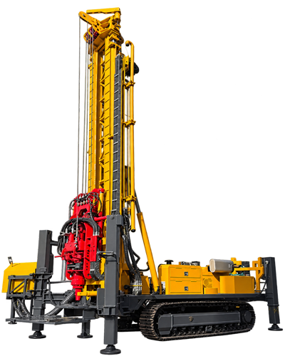
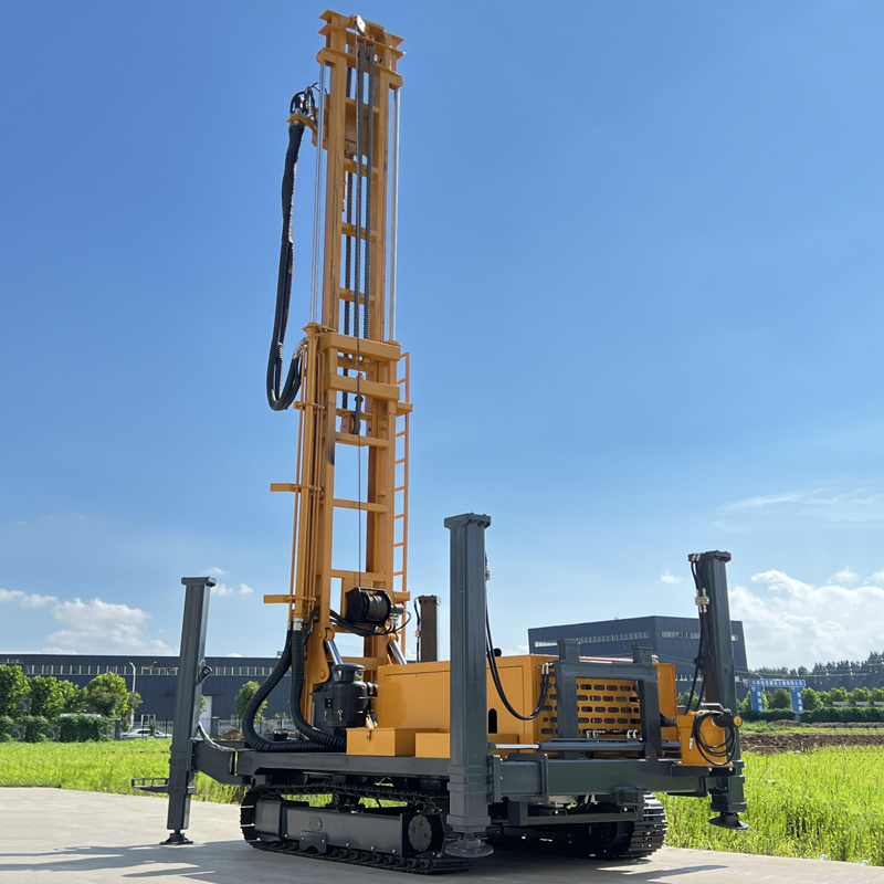
After the equipment class is determined, it is also necessary to verify whether it can reach the hole location and whether it can be set up. The WR450SE complete machine weighs approximately 8.5 T, has overall dimensions of approximately 5.85 × 1.8 × 2.4 m, a travel speed of approximately 2.5 km/h, and a maximum climbing angle reference of 21°. The crawler structure is suitable for village roads, gravel ground, and generally uneven ground, but ground bearing capacity and slope conditions must still be confirmed before transfer, and movement should be cautious in soft soil and wet slippery areas.
The hydraulic outrigger stroke is 1.6 m, used for leveling and stable support on mildly uneven sites. Mid-deep hole construction cycles are relatively long, and pad plates should be used on soft ground to prevent outrigger settlement. These are on-site preparation items and cannot be replaced by equipment selection.
Items still requiring confirmation with the manufacturer or project owner
- Whether the target aquifer depth and expected water yield are supported by local hydrogeological data, rather than estimated only from neighboring well experience.
- Whether the completed well diameter, well casing specifications, and submersible pump outer diameter have been determined, and whether the drilling tool and filter pipe configuration can correspond.
- What proportion of the main formation combination is loose layer versus rock layer, and based on this determine the combination of mud pump, air compressor, and DTH hammer.
- Whether the power supply is stable and whether a generator needs to be selected; whether the air compressor pressure and displacement match the selected DTH hammer.
- The road bearing capacity and slope of the transfer route between hole locations, especially in rainy seasons or soft soil areas.
- Whether to choose the 1.1 T standard configuration or the 2.5 T optional configuration for the auxiliary winch depends on the actual weight of accessories such as DTH hammers and casing.
Before these conditions are implemented, judging the equipment class solely by the drilling depth figure can easily lead to discovering after start-up that the supporting equipment does not match.